|
|
||||||||
| |
|
|
|
|
|
|
|
|
| |
||||||||
| |
|
||||||||||||
| |
 |
||||||||||||
| |
|||||||||||||
| |
DARTFORD RIVER CROSSING: INNOVATION IN CIVIL ENGINEERINGINTRODUCTIONThe Crossing is situated some 20 miles east of London and carries the M25 motorway traffic across the River Thames between Dartford in Kent and Thurrock in Essex. Two tunnels each 1.4 kilometres long carry four lanes of traffic northbound, and the Queen Elizabeth II Bridge, 2.8 kilometres long carries four lanes of traffic southbound. Dartford River Crossing's area of operational responsibility extends from Junction 31 in the north to Junction 2 in the south, a distance of approximately 9 kilometres. The Dartford River Crossing is open 24 hours a day, every day throughout the year. |
||||||||||||
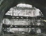
THE TWO TUNNELSThe first crossing of the River Thames at Dartford was a twin lane bored tunnel which opened in November 1963 as a local link between the A2 and A13. A Joint Committee from Kent and Essex County Councils was responsible for its operation and maintenance. Construction took five years as work was hampered by difficult tunneling conditions in the chalk. On opening, traffic was over 4m vehicles per year or 12,000 vehicles per day. This increased steadily over the following years until in the early 1970s it was running at over 10m vehicles per year. The Joint Committee decided that traffic levels warranted a second tunnel of similar capacity and construction began in 1972. Again, the difficult ground conditions prolonged construction and the second tunnel did not open until May 1980.
Traffic was now 11 million vehicles per year or 30,000 vehicles per day. Capacity was not a problem until 1984 when sections of the M25 London Orbital Motorway began to be opened. In 1984 the County Councils asked the Government to take over responsibility for the tunnels as part of the national motorway network. The Secretary of State for Transport commissioned a traffic report, which forecast that the existing tunnels would be overloaded to an unacceptable degree by the early 1990s. |
|||||||||||||
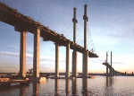
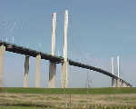
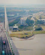
THE QE2 BRIDGEIn March 1986 the Department of Transport gave permission to Dartford River Crossing Limited to take over the two existing tunnels discharging the outstanding debts of the Kent and Essex County Councils, to design and build a new four lane cable stayed bridge and to maintain and operate the combined Crossing for a maximum period of 20 years. Riverside sites like that at Swanscombe seem to have been especially favoured by these early Clactonian people. Wild animals came to drink on the banks of the river channels, and could be easily hunted. The river environment also provided a rich variety of plants and aquatic species.
Work on the bridge commenced in August, 1988 immediately after the Company took over the operation of the existing tunnels under the terms of the Concession Agreement, and was officially opened by Her Majesty the Queen in October 1991, on time and within budget. The 2872 metre bridge comprises a 812 metre cable stayed bridge with a 450 metre main span and approach viaducts of 1052 metres on the Essex side and 1008 metres on the Kent side. The Queen Elizabeth II Bridge marked the first fully privatised infrastructure project in the United Kingdom in the 20th Century. Since the opening of the Bridge in October 1991 traffic has grown by some 75%, and current traffic levels are now in excess of 50 million vehicles annually. |
|||||||||||||
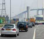
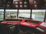
TRAFFIC OPERATIONSThe Traffic Control Operations Centre, overlooking the toll plazas on the Kent side monitors and supervises a sophisticated array of equipment ensuring the safe and efficient flow of traffic through the Crossing. CCTV cameras provide an instant and continuous view of traffic conditions
on both approach roads, in the tunnels and on the bridge. A radio system
allows communication with staff and an internal telephone system allows
communication throughout the Crossing and includes emergency phones at
regular intervals in the tunnels and on the bridge. This communications
network enables a rapid response to any incident and ensures maximum standards
of safety are maintained at all times. In the tunnels, monitoring systems measure vehicle exhaust emissions to ensure the correct level of ventilation is maintained. On the bridge, sensors buried within the road deck measure surface and air temperatures; anemometers at mid-span and on the pylons measure wind speed and direction.
In high wind the system allows a progressive series of measures to be applied to restrict the speed and position of vehicles on the bridge, to divert high sided vehicles through one of the tunnels and finally at very high wind speeds to close the bridge and send all the traffic through the tunnels. Within the tunnels, lights are fed alternately from the Kent and Essex electricity supplies in order that if either supply fails the tunnels will still remain evenly lit along their lengths. Lighting on the bridge had to be designed with aircraft and shipping in mind, as well as road traffic. Street lighting illuminates the road deck at night. In addition aircraft warning lights are located on the pylons and navigation lights and radar reflectors mark the shipping navigation channel.
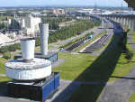
Ventilation of the tunnels is critical for users both during peak traffic times or in an emergency situation such as a fire within a tunnel. Fresh air is generated by fans situated in buildings at ground level on both sides of the river, and fed into the traffic space by means of under road ducts which extend between the two ventilation shafts. Exhaust fans are also situated in the same buildings, above the crown of the tunnel to take away foul air. If a fire did take place, jet fans located in the tunnel roof provide a high, forward air flow to prevent smoke and fumes affecting users behind the incident. Pumping systems ensure that any water seeping into the tunnels and rainwater running off the bridge approach viaducts is diverted after treatment into the River Thames. |
|||||||||||||
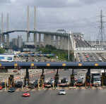
COLLECTING THE TOLLSSteps have also been taken to ensure the toll collection system has the capacity to deal with the increased volume of traffic. In 1991 a completely new integrated toll system was installed comprising manual toll terminals, automatic coin machines, and an automatic vehicle identification system known as DART-Tag. DART-Tag is a computer chip based device approximately the size of a tax disc which is fixed to the inside of a vehicle windscreen. As the vehicle approaches a toll booth an antenna at the booth sends a signal to the tag, which returns the signal identifying itself to the toll system.Tolls are collected in both the northbound and southbound directions using two toll plazas located on the Kent side comprising 14 lanes northbound and 13 lanes southbound. Next topic: Arts
|
|||||||||||||